Operating Systems
The more you know about operating system, the better you can cooperate with it.
Operating System Overview
Role
Role 1
The Operating System is an Abstract Machine
- Extends the basic hardware with added functionality
- Provides high-level abstractions
- More programmer friendly
- Common core for all applications
- It hides the details of the hardware
- Makes application code portable
Role 2
The Operating System is a Resource Manager
- Responsible for allocating resources to users and processes
- Must ensure
- No Starvation
- Progress
- Allocation is according to some desired policy
- First-come, first-served; Fair share; Weighted fair share; limits (quotas), etc…
- Overall, that the system is efficiently used
Structural (Implementation) View
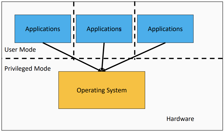
the Operating System is the software Privileged mode.
Operating System Kernel
- Portion of the operating system that is running in privileged mode
- Usually resident (stays) in main memory
- Contains fundamental functionality
- Whatever is required to implement other services
- Whatever is required to provide security
- Contains most-frequently used functions
- Also called the nucleus or supervisor
The Operating System is Privileged
Applications should not be able to interfere or bypass the operating system
OS can enforce the “extended machine”
OS can enforce its resource allocation policies
Prevent applications from interfering with each other
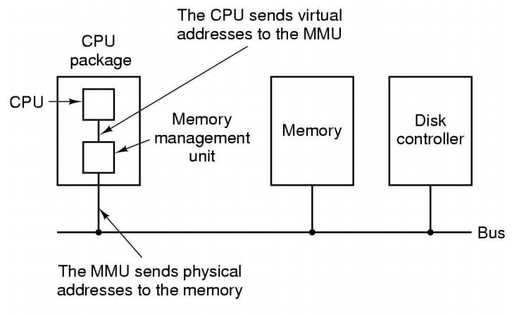
The Structure of a Computer System
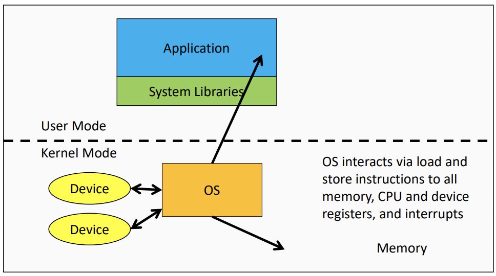
- Applications interact with themselves and via function calls to library procedures
- OS and application interacts via System calls
A Note on System Libraries
System libraries are just that, libraries of support functions (procedures, subroutines)
Only a subset of library functions are actually system calls, and system call functions are in the library for convenience
Privilege-less OS
Can implement OS functionality, but cannot enforce it.
Some Embedded OSs have no privileged component
- All software runs together
- No isolation
- One fault potentially brings down entire system
Operating System Software
Fundamentally, OS functions the same way as ordinary computer software.
- It is machine code that is executed (same machine instructions as application).
- It has more privileges (extra instructions and access).
Operating system relinquishes control of the processor to execute other programs, it reestablishes control after
- System calls
- and Interrupts (especially timer interrupts).
Operating System Internal Structure
The Monolithic Operating System Structure, Also called the “spaghetti nest” approach(Everything is tangled up with everything else. )
Processes and Threads
Major Requirements of an Operating System
- Interleave the execution of several processes to maximize processor utilization while providing reasonable response time
- Allocate resources to processess
- Support interprocess communication and user creation of processes
Processes and Threads
Processes
- Also called a task or job
- Execution of an individual program
- “Owner” of resources allocated for program execution
- trace the usage of processes, clean up memory after finishing execution
- Encompasses one or more threads
Threads
The sequence of execution through an application
- Unit of execution
- Can be traced
- list the sequence of instructions that execute
- Belongs to a process
- Process provide environment, and all thread running in the process share the environment
- Executes within it
Process
The Process Model
Single process machine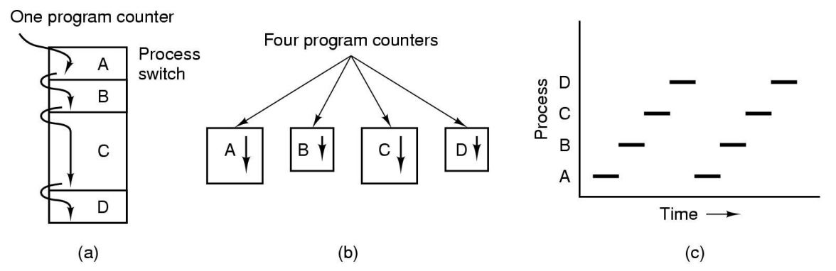
- Multiprogramming of four programs
- Conceptual model of 4 independent, sequential processes(with a single thread each)
- Only one program active at any instant

the box represents a process, and the line represents the thread and the dotted lines represent what the OS can do
Process and thread models of selected OSes
- Single process, single thread
- MSDOS
- Signle process, multiple threads
- OS/161 as distributed
- Multiple processes, single thread
- Traditional UNIX
- Multiple processes, multiple threads
- Modern Unix(Linux, Solaris), Windows
Process Creation
Principal events that cause process creation
- System initialization
- Foreground processes(interactive programs)
- Background processes
- Email server, web server, print server, etc.
- Called a daemon(unix) or service(Windows)
- Execution of a process creation system call by running a process
- New login shell for an incoming ssh connection
- User request to create a new process
- Initiation of a bach job
Note: Technically, all these cases use the same system machanism to create new processes
Process Termination
Conditions which terminate processes
- Normal exit(voluntary)
- Error exit(voluntary)
- Fatal error(involuntary)
- e.g. segmentation fault
- Killed by another process(involuntary)
Implementation of Processes
- A processes’ information is stored in a process control block(PCB)
- The PCBs form a process table
- Reality can be complex(hashing, chaining, allocation bitmaps,…)
- Size can be dynamic
Example fields of a process table entry
| Process Management | Memory management | File management |
|---|---|---|
| Registers | Pointer to text segment | Root directory |
| Program counter | Pointer to data segment | working directory |
| Program status word | Pointer to stack segement | File descriptors |
| Stack pointer | User ID | |
| Process state | Group ID | |
| Priority | ||
| Scheduling parameters | ||
| Process ID | ||
| Parent process | ||
| process group | ||
| Signals | ||
| time when process started | ||
| CPU time used | ||
| Children’s CPU time | ||
| Time of next alarm |
Process/Thread States
Three states process model(the minial model the OSes implement)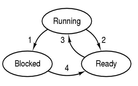
In the image the numbers prepresent:
- Process blocks for input
- Scheduler picks another process
- Scheculer picks this process
- Input becomes available
- Possible process/thread states
- running
- blocked
- ready
Generally, if no IO, processes almost all sitting in running and ready
- Transitions between states shown
some Transition Causing Events
- Running -> Ready
- Voluntary Yield()
- End of timeslice
- Running -> Blocked
- Waiting fot input
- File, network,
- Waiting for a timer(alarm signal)
- Waiting for a resource to become available
- Waiting fot input
Scheduler
responsible for want to run next
- Sometimes alse called the dispatcher
- The literature is alse a little inconsistent on with terminology
- Has to choose a Ready process to run
- It is inefficent to search through all processes
The Ready Queue
What about blocked processes
When an unblocking event occurs, we also wish to avoid scanning all processes to select one to make Ready
using two queues(One option)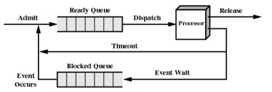
another option(using a queue for every event)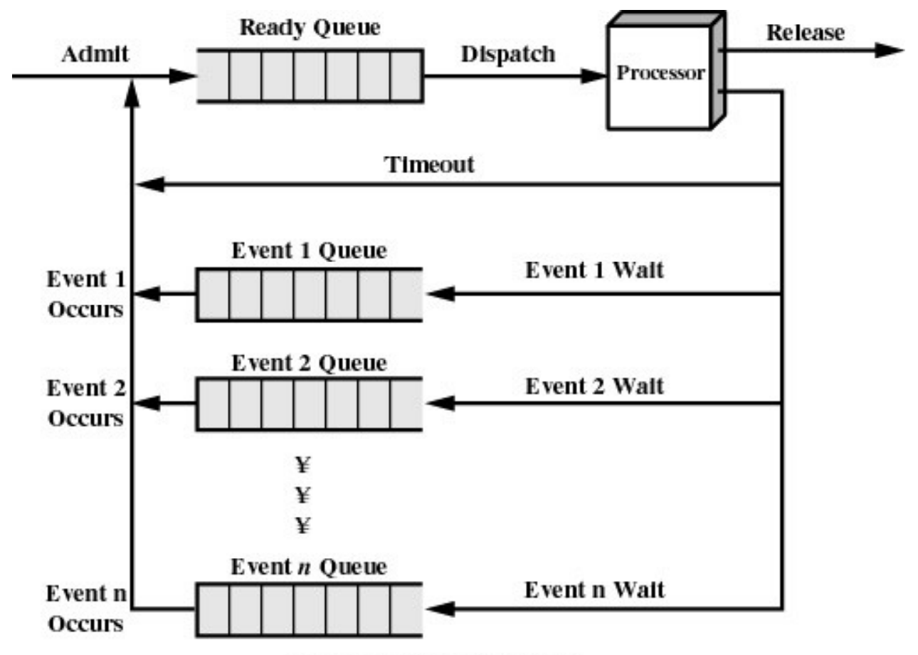
Implementation
- Minimally consist of three segments
- Text
- contains the code (instructions)
- Data
- Global variables
- Stack
- Activation records of procedure/function/method
- Local variables
- Text
- User-mode
- Processes (programs) scheduled by the kernel
- Isolated from each other
- No concurrency issues between each other
- System-calls transition into and return from the kernel
- Kernel-mode
- Nearly all activities still associated with a process
- Kernel memory shared between all processes
- Concurrency issues exist between processes concurrently executing in a system call
Thread
The Thread Model
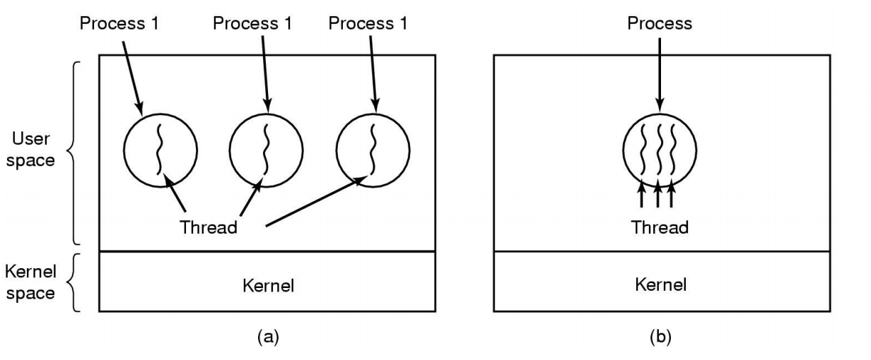
(a) Three processes each with one thread
(b) One process with three thread
Separating execution from the environment
| Per process items | Per thread items |
|---|---|
| Address space | Program counter |
| Global variables | Registers |
| Open files | Stack |
| Child processess | State |
| Pending alarms | |
| Signals and signal handlers | |
| Accounting information |
Items shared by all threads in a process
Item private to each thread
The Thread Model
- State implicitly stored on the stack
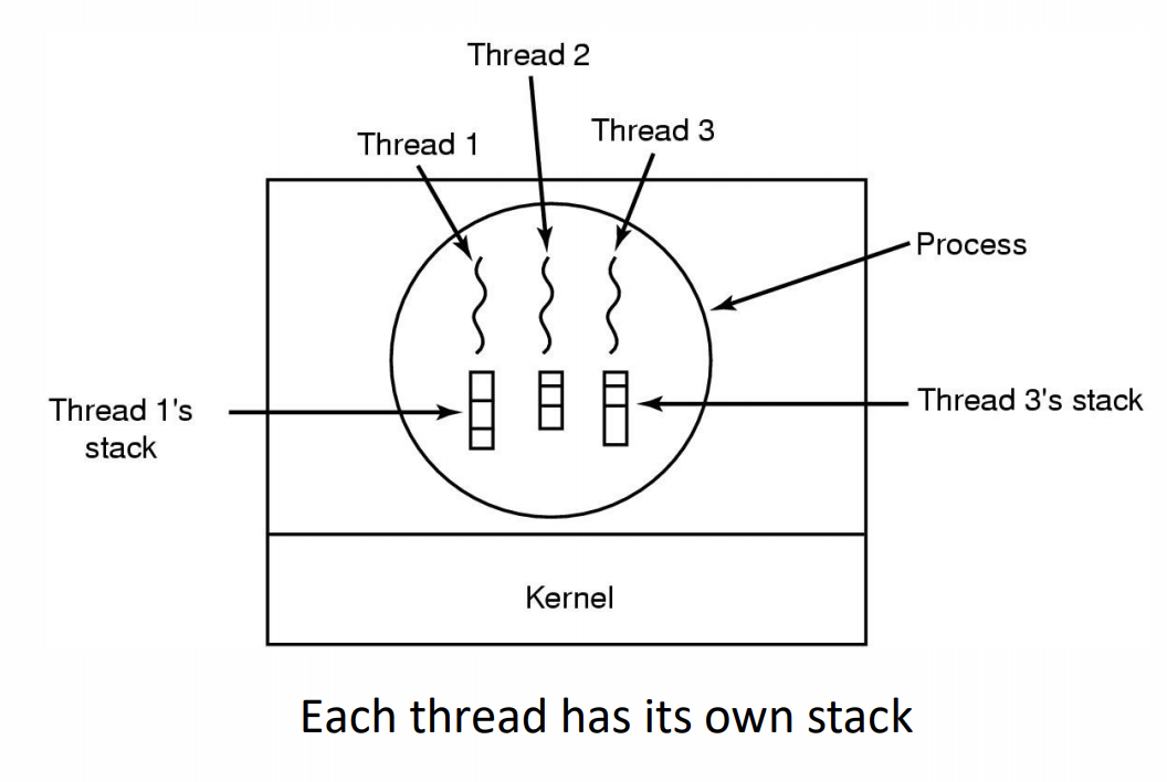
- Local variables are per thread
- Allocated on the stack
- Don’t have concurrency issues
- Global variables are shared between all threads
- Allocated in the data section
- Concurrency control is an issue
- Dynamically allocated memory(malloc) can be glocal or local
- Program defined(the pointer can be global or local)
- If the pointer is global variable(has concurrency issue) while locals don’t
Thread Usage
Example
1 | // dispatcher thread |
| Model | Characteristics |
|---|---|
| Threads | Parallelism, blocking system calls |
| Sigle-threaded process | No parallelism, blocking system calls |
| Finite-state machine | Parallelism, nonblocking system calls, interrupts |
Why Threads?
- Simpler to program than a state machine
- Less resources are associated with them a complete process
- Cheaper to create and destory
- Shares resources(especially memory) between them
- Performace: Threads waiting for I/O can be overlapped with computing threads
- Note if all threads are compute bound, then there is no performance improvement(on a uniprocessor)
- Threads can take advantage of the parallelism available on machines with more than one CPU(multiprocessor)
User-level Threads
- Implementation at user-level
- User-level Thread Control Block (TCB), ready queue, blocked queue, and dispatcher
- Kernel has no knowledge of the threads (it only sees a single process)
- If a thread blocks waiting for a resource held by another thread inside the same process, its state is saved and the dispatcher switches to another ready thread
- Thread management (create, exit, yield, wait) are implemented in a runtime support library
- Pros
- Thread management and switching at user level is much faster than doing it in kernel level
- No need to trap (take syscall exception) into kernel and back to switch
- Dispatcher algorithm can be tuned to the application
- Can be implemented on any OS (thread or non-thread aware)
- Can easily support massive numbers of threads on a per-application basis
- Use normal application virtual memory
- Kernel memory more constrained. Difficult to efficiently support wildly differing numbers of threads for different applications.
- Thread management and switching at user level is much faster than doing it in kernel level
- Cons
- Threads have to yield() manually (no timer interrupt delivery to userlevel)
- Co-operative multithreading
- A single poorly design/implemented thread can monopolise the available CPU time
- There are work-arounds (e.g. a timer signal per second to enable preemptive multithreading), they are course grain and a kludge.
- Co-operative multithreading
- Does not take advantage of multiple CPUs (in reality, we still have a single threaded process as far as the kernel is concerned)
- If a thread makes a blocking system call (or takes a page fault), the process (and all the internal threads) blocks
- Can’t overlap I/O with computation
- Threads have to yield() manually (no timer interrupt delivery to userlevel)
Kernel-level threads
Cons
- Thread creation and destruction, and blocking and unblocking threads requires kernel entry and exit.
- More expensive than user-level equivalent
- Thread creation and destruction, and blocking and unblocking threads requires kernel entry and exit.
Pros
- Preemptive multithreading
- Parallelism
- Can overlap blocking I/O with computation
- Can take advantage of a multiprocessor
Context Switch
A context switch can refer to a switch between threads, involving saving and restoring of state associated with a thread; A switch between processes, involving the above, plus extra state associated with a process.
Context Switch Occurrence
A switch between process/threads can happen any time the OS is invoked
- On a system call
- Mandatory if system call blocks or on exit()
- On an exception
- Mandatory if offender is killed
- On an interrupt
- Triggering a dispatch is the main purpose of the timer interrupt
A thread switch can happen between any two instructions
Note instructions do not equal program statements
Context Switch
- Context switch must be transparent for processes/threads
- When dispatched again, process/thread should not notice that something else was running in the meantime (except for elapsed time)
- OS must save all state that affects the thread
- This state is called the process/thread context
- Switching between process/threads consequently results in a context switch.
Concurrency and Synchronisation
Concurrency Example
1 | // count is a global variable shared between two threads |
Have a race condition. Occurred when global variables shared by threads
There is in-kernel concurrency even for single-threaded process
The OS has to deal with concurrency even if it is a single thread application.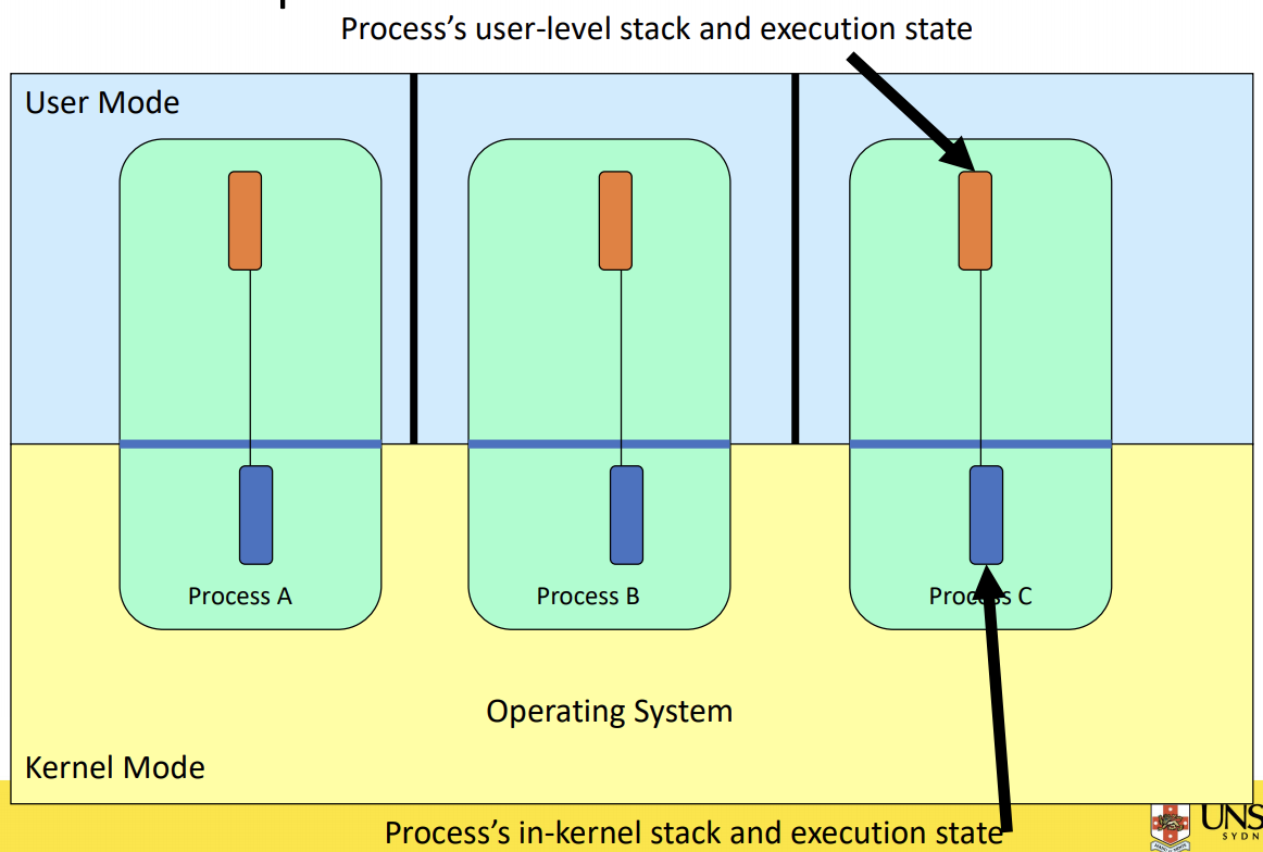
Critical Region
- We can control access to the shared resource by controlling access to the code that accesses the resource
A critical region is a region of code where shared resources are accessed(e.g. Variables, memory, files, etc…)
- Uncoordinated entry to the critical region results in a race condition
- => Incorrect behavior, deadlock, lost work,…
Indentifying critical regions
- Critical regions are regions of code that:
- Access a shared resource,
- and correctness relied on the shared resource not being concurrently modified by another thread/process/entity.
1 | // count is a global variable shared between two threads |
if we can make the critical regions never overlap, we won’t have concurrency problem.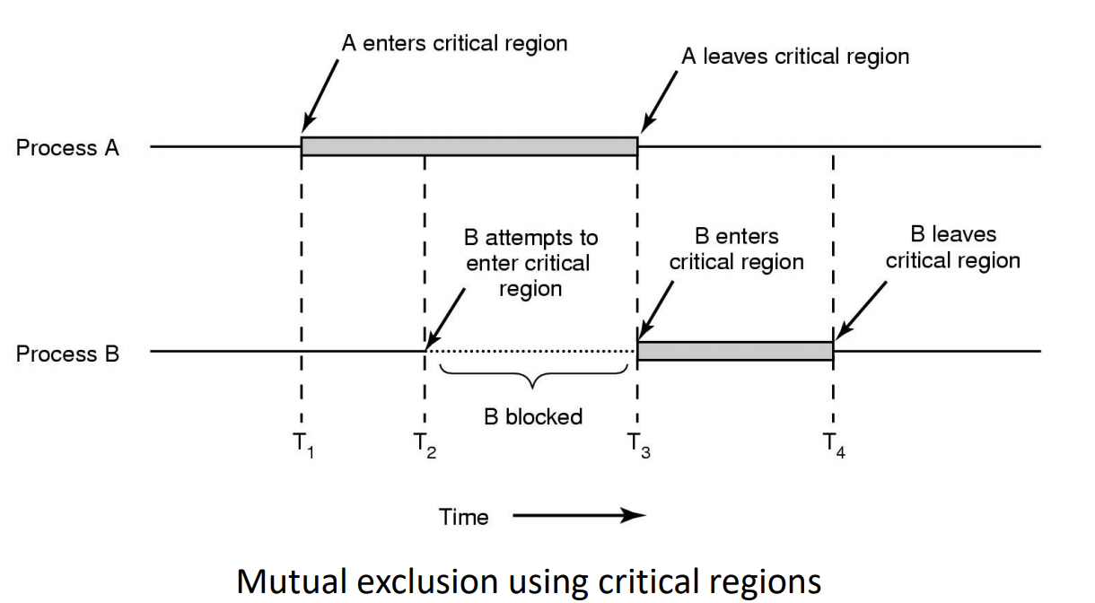
Example critical regions
1 | struct node { |
- Race example
1 | // thread 1 |
one possible sequence: 1 -> 3 -> 2 -> 4, then the item in thread 1 is lost(seg fault)
both1-2 and 3-4 are critical regions
Critical regions solutions
- We seek a solution to coordinate access to critical regions
- Also called critical sections
- Conditions required of any solution to the critical region problem
- Mutual Exclusion: No two processes simultaneously in critical region
- No assumptions made about speeds or numbers of CPUs
- Progress
- No process running outside its critical region may block another process
- Bounded
- No process waits forever to enter its critical region
A solution?
- A lock variable
- if lock == 1, somebody is in the critical section and we mush wait
- if lock == 0, nobody is in the critical section and we are free to enter
1 | // A problematic execution sequence |
In the example above, there is race contition between the observation that the lock variable is not one and setting the lock to prevent somebody else from entering.
Mutual Exclusion by Taking Turns
1 | while (TRUE) { |
This example works because the update is only been updated by the thread having its turn.
- Works due to strict alternation
- Each process takes turns
- Cons
- Busy waiting(loop)
- sol: not my turn, do sth else, come back to my turn
- Process must wait its turn even while the other process is doing something else.
- With many processes, must wait for everyone to have a turn
- Does not guarantee progress if a process no longer needs a turn
- Poor solution when processes require the critical section at differing rates
- With many processes, must wait for everyone to have a turn
- Busy waiting(loop)
Mutual Exclusion by Disabling Interrupts
only used in very short critical sections, because it prespond other devices in the machine and make them less responsive
- Before entering a critical region, disable interrupts
- After leaving the critical region, enable interrupts
- Pros
- simple
- Cons
- Only available in the kernel
- Blocks everybody else, even with no contention
- slows interrupt response time
- Does not work on a multiprocessor
Hardware Support for mutual exclusion
- Test and set instruction
- can be used to implement lock variables correctly
- It loads the value of the lock
- If lock == 0,
- set the lock to 1
- return the result 0 – we acquire the lock
- If lock == 1
- return 1 – another thread/process has the lock
- can be used to implement lock variables correctly
- Hardware guarantees that the instruction executes atomically(atomically: as an indivisible unit)
1 | enter_region: |
- Pros
- Simple(easy to show it’s correct)
- Available at user-level
- To any number of processors
- To implement any number of lock variables
- Cons
- Busy waits(also termed a spin lock)
- consumes CPU
- starvation is possible when a process leaves its critical section and more than one process is waiting
- Busy waits(also termed a spin lock)
Tackling the Busy-Wait Problem
- Sleep / Wake up
- The idea
- When process is waiting for an event, it calls sleep to block, instead of busy waiting
- The event happens, the event generator(another process) calls wakeup to unblock the sleeping process.
- Walking a ready/running process has no effect
- The idea
The producer-Consumer Problem
Also called the bounded buffer problem
A producer produces data items and stores the items in a buffer
A consumer takes the items out of the buffer and consumes them.
- two problems: Concurrency(because shared resource) and the producer should be blocked when the buffer is full and the consumer should be blocked when the buffer is empty.
- We must keep accurate count of items in the buffer
- The consumer can call wakeup when it consumes the first entry of the full buffer
- The Producer can call wakeup when it adds the first item to the buffer
Semaphores
- Dijkstra introduced two primitives that are more powerful than simple sleep and wakeup alone.
- P(): proberen, from Dutch to test
- V(): verhogen, from Dutch to increment
- Also called wait & signal, down & up
How do they work
- If a resource is not available, the corresponding semaphore blocks any process waiting for the resource
- Blocked processes are put into a process queue maintained by the semaphore(avoids busy waiting)
- When a process releases a resource, it signals this by means of the semaphore
- Signalling resumes a blocked process if there is any
- Wait(P) and signal(V) operations cannot be interrupted
- Complex coordination can be implemented by multiple semaphores
Semaphore implementation
- Define a semaphore as a record
Each primitive is atomit(wait and signal), the OS would use the disabling of interrupts in the implementation of Semaphore inside the OS.
1 | typedef sturct { |
Semaphore as a General Synchronization Tool
- Execute B in Pj only after A executed in Pi
- Use semaphore count initlialized to 0
- Code:
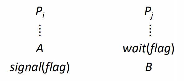
- A first: signal(count is 1) -> then B runs(count is 0) -> A(this is what we want)
- B first: wait(count < 0, sleep) -> A runs, wake up B(still what we want)
Semaphore implementation of a Mutex
- Mutex is short for Mutual Exclusion
- Can also be called a lock
1 | semaphore mutex; |
Notice that the inital count determines how mant waits can progress before blocking and requiring a signal => mutex.count initialised as 1
Solve the producer-consumer problem
1 |
|
Summary
- Semaphores can be used to solve a varity of concurrency problems
- However, programming with then can be error-prone
- E.g. must signal for every wait for mutexes
- Too many or few signals or waits, or signals and waits in the wrong order, can have catastrophic results
- E.g. must signal for every wait for mutexes
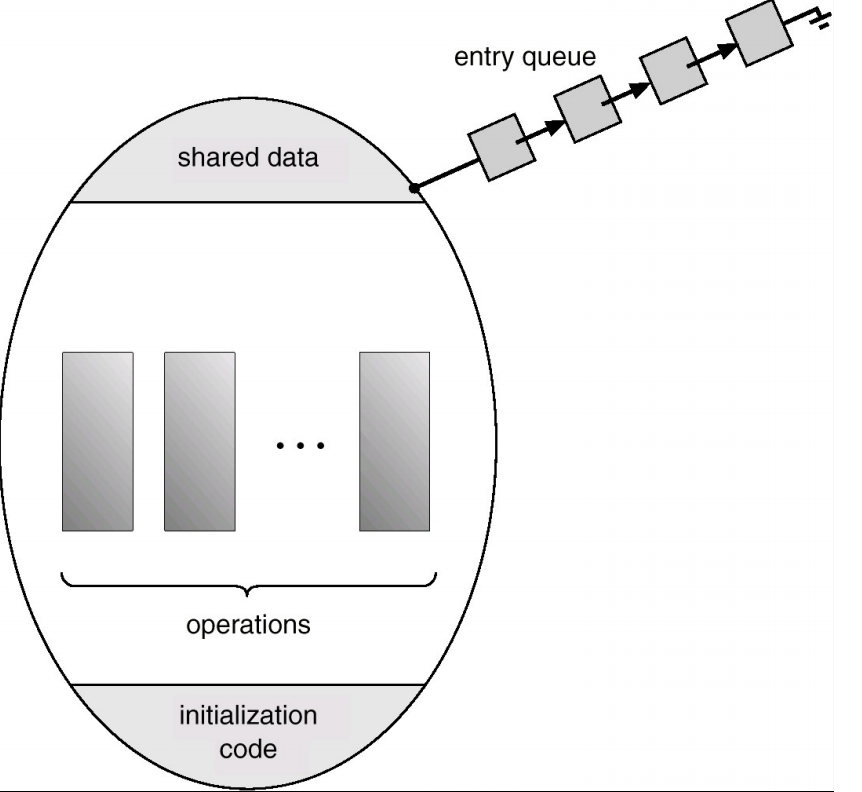
Monitors
- To ease concurrent programming, Hoare(1974) proposed monitors
- A higher level synchronisation primitive
- Programming language construct
- Idea
- A set of procedures, variables, data types are grouped in a special kind of module, a monitor.
- Variables and data types only accessed from within the monitor
- Only one process/thread can be in the monitor at any one time
- Mutual exclusion is implemented by the compiler(which should be less error prone)
- Mutual exclusion is implemented by the compiler(which should be less error prone)
- A set of procedures, variables, data types are grouped in a special kind of module, a monitor.
- When a thread calls a monitor procedure that has a thread already inside, it is queued and it sleeps until the current thread exits the monitor
example
1 | monitor exmaple |
How do we block waiting for an event?
- We need a mechanism to block waiting for an event( in addition to ensuring mutual exclusion)
- for producer consumer problem, when buffer is empty or full
- Condition variables
- To allow a process to wait within the monitor, a condition variable must be declared, as
condition x, y - Condition variable can only be used with the operations wait and sigal
- The operation
x.wait();- means that the process invoking this operation is suspended until another process invokes
- Another thread can enter the monitor while original is suspended
x.signal();- The operation resumes exactly on suspended process. If no process is suspended, then the signal opeartion has no effect.
- The operation
- To allow a process to wait within the monitor, a condition variable must be declared, as
The Readers and Writers Problem
- Models access to a data base
- E.g. airline reservation system
- Can have more thant one concurrent reader
- To check schedules and reservations
- Writers must have exclusive access
- To book a ticket or update a schedule
A solution
1 | typedef in semaphore; /* use your imagination */ |
Deadlock
Resources
- Examples of computer resources
- printers
- tape drives
- Tables in a database
- Processes need access to resources in reasonable order
- Preemptable resources
- e.g. virtual memory
- can be taken away from a process with no ill effects
- Nonpreemtable resources
- will cause the process to fail if take away
Resources & Deadlocks
- Suppose a process holds resource A and requests resource B
- at same time another process holds B and requests A
- both are blocked and remain so – Deadlock
- Deadlocks occur when …
- processes are granted exclusive access to devices, locks, tables, etc..
- we refer to these entities generally as resources
Resource Access
- Sequence of events required to use a resource
- request the resource
- use the resource
- release the resource
- Must wait if request is denied
- requesting process may be blocked
- may fail with error code
Deadlock
A set of processes is deadlocked if each process in the set is waiting for an event that only another process in the set can cause.
- Usually the event is release of a currently held resource
- None of the processes can …
- run
- release resources
- be awakened
Four Conditions for Deadlock
- Mutual exclusion condition
- each resource assigned to 1 process or is available
- Hold and wait condition
- process holding resources can request additional
- No preemption condition
- previously granted resources cannot be forcibly taken away
- Circular wait condition
- must be a circular chain of 2 or more processes
- each is waiting for resource held by next member of the chain
Strategies for dealing with Deadlocks
Just ignore the problem altogether
prevention
Negating one of the four necessary conditions
Detection and recovery
Dynamic avoidance
Careful resource allocation
Appoarch 1: The Ostrich Algorithm
- Pretend there is no problem
- Reasonable if
- deadlocks occur very rarely
- Cost of prevention is high
- Example of “cost”, only one process runs at a time
- UNIX and Windows takes this approach for some of the more complex resource relationships they manage
- It’s a trade off between
- Convenience (engineering approach)
- Correctness(mathematical approach)
Approach 2: Deadlock Prevention
The most common used strategy
Resource allocation rules prevent deadlock by prevent one of the four condition required for deadlock from occuring
Mutual exclusion
- Not feasible in general
- Some devices/resource are intrinsically not shareable
- Not feasible in general
Hold and wait
Require processes to request resources before starting
- a process never has to wait for what it needs
Issues
may not know required resources at start of run
must be determined at run time or by user input(e.g. using Word to open a file)
$\Rightarrow$ not always possible
Also ties up resources other processes could be using
Varitions:
Process must give up all resources if it would block holding a resource
then request all immediately needed
prone to livelock
Livelocked processes are not blocked, change state regularly, but never make progress.
No preemption
- This is not a viable option
Circular Wait
- aquire resource in the same order, order resources
Approach 3: Detection and Recovery
- Need a method to determine if a system is deadlocked
- Assuming deadlocked is detected, we need a method of recorvery to restore progress to the system.
Modeling resources and processes as a directed graph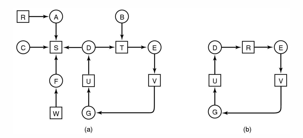
(a) represents everthing in the system
(b) is a deadlock
What about resources with multiple units?
- Some examples of multi-unit resources
- RAM
- Blocks on a hard disk drive
- Slots in a buffer
- We need an approach for dealing with resources that consists of more than a single unit
Modeling using matrix
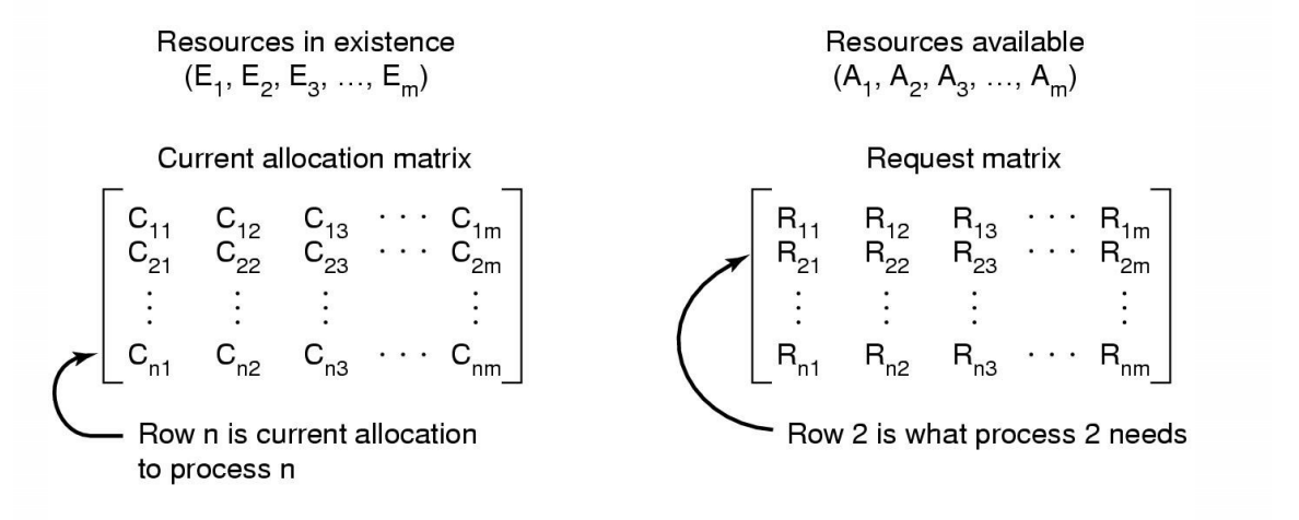
Data structured needed by deadlock detection algorithm
sum of current resource allocation + resources available = resources that exist
$$
\sum_{i=1}^{n}{C_{ij}}+A_j = E_j
$$Example
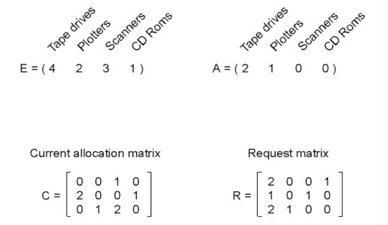
- Process 1: has 1 scanners
- Process 2: has 2 tape drivers and 1 CD roms
- Process 3: has 1 plotters and 2 scanners
Detection Algoritm
- Look for an unmarked process $Pi$, for which the $i$-th row of R is less than equal to A
- If found, add the $i$-th row of C to A, and mark $Pi$. Got to step 1
- If no such process exists, terminate
Remaining processes are deadlocked.
Recovery from Deadlock
- Recovery through preemption
- Take a resource from some other process
- Depends on nature of the resource
- Recovery through rollback
- Checkpoint a process periodically
- not come for free, not practical
- Use this saved state
- Restart the process if it is found deadlocked
- No guarantee is won’t deadlock again
- Checkpoint a process periodically
- Recovery through killing processes
- Crudest but simplest way to break a deadlock
- Kill one of the processes in the deadlock cycle
- The other processes get its resources
- Choose process that can be rerun from the beginning
Approach 4 Deadlock Avoidance
Not practical for all systems, need to know enough information in advance
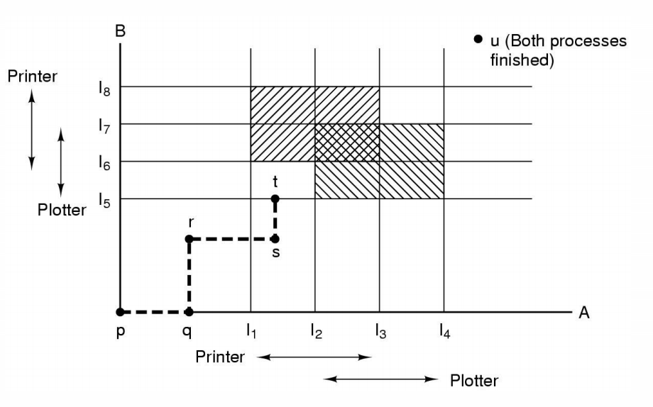
Safe and Unsafe States
- A state is safe if
- The system is not deadlocked
- There exists a scheduling order that results in every process running to completion, even if they all request their maximum resources immediately
- Unsafe states are not necessarily deadlocked
- with a lucky sequence, all processes may complete
- However, we cannot guarantee that they will complete(not deadlock)
- Safe states guarantee we will eventually complete all processes
- Deadlock avoidance algorithm
- Only grant requests that result in safe states
Bankers Algorithm
- Modelled on a Banker with Customers
- The banker has a limited amount of money to loan customers
- Limited number of resources
- Each customer can borrow money up to the customer’s credit limit
- Maximum number of resources required
- The banker has a limited amount of money to loan customers
- Basic idea
- keep the bank in a safe state
- So all customers are happy even if they all request to borrow up to their credit limit at the same time
- Customers wishing to borrow such that the back would enter an unsafe state must wait until somebody else repays their loan such that the transaction becomes safe.
- keep the bank in a safe state
- Bankers Algorithm is not commonly used in practice
- It is difficult (sometimes impossible ) to know in advance
- the resources a process will require
- the number of processes in a dynamic system
- It is difficult (sometimes impossible ) to know in advance
Starvation
A process never receives the resource it is waiting for, despite the resource(repeatedly) becoming free, the resource is always allocated to another waiting process.
One solution: First-come, first-serve policy
System Call
System Calls
- Can be viewed as special function calls
- Provides for a controlled entry into the kernel
- While in kernel, they perform a privileged operation
- Returns to original caller with the result
- The system call interface represents the abstract machine provided by the operating system.
A brief overview
From the user’s perspective
- Process Management
- File I/O
- Dirctories management
- Some other selected Calls
- There are many more
- On Linux, see man syscalls for a list
Process Management
| Call | Descritption |
|---|---|
| pid=fork() | Create a child process identical to the parent |
| Pid = waitpid(pid, &statloc, options) | Wait for a child to terminate |
| s = execve(name, argv, environp) | Replace a process’ core image |
| exit(status) | Terminate process execution and return status |
File Management
| Call | Descrition |
|---|---|
| fd=open(file, how, …,) | Open a file for reading, writing or both |
| s = close(fd) | Close an open file |
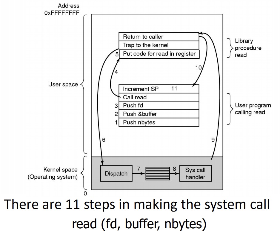
| n = read(fd, buffer, bytes) | Read data from a file into a buffer |
| n = write(fd, buffer, bytes) | Write data from a buffer into a file |
| Position = lseek(fd, offset, whence) | Move the file pointer |
| s = stat(name, &buf) | Get a file’s status information |
A stripped down shell:
1 | while(TRUE) { /* repeat forever */ |
System Call Implementation
A Simple Model of CPU Computation
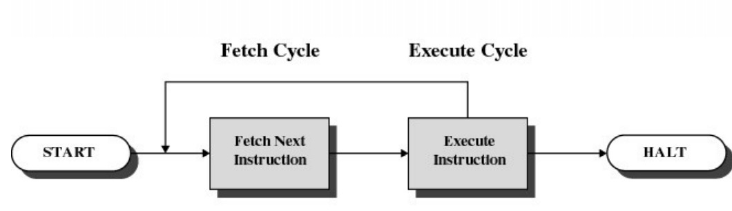 The fetch-execute cycle
- Load memory contents from address in program counter (PC)
- The instruction
- Execute the instruction
- increment PC
- Repeat
A Simple Model of CPU Computation
Stack Pointer(SP)
Status Register
Condition codes
- Positive result
- Zero result
- Negative result
General Purpose Register
- Holds operands of most instructions
- Enables programmers (compiler) to minmise memory reference
Privileged-mode Operation
To protect operating system execution, two or more CPU modes of operation exist
- Privileged mode(system, kernel-mode)
- All instructions and register are available
- User-mode
- Users ‘safe’ subset of instruction set
- Only affects the state of the application itself
- They cannot be used to uncontrollably interference with OS
- Only ‘safe’ registers are accessible
- Users ‘safe’ subset of instruction set
System Call
System Call Mechanism Overview
- System call transitions triggered by special processor instructions
- User to Kernel
- System call instruction
- Kernel to User
- Return from privileged mode instruction
- User to Kernel
- Processor mode
- Switched from user-mode to kernel-mode
- Switched back when returning to user mode
- Switched from user-mode to kernel-mode
- Stack Pointer (SP)
- User-level SP is saved and a kernel SP is initialised
- User-level SP restored when returning to user-mode
- User-level SP is saved and a kernel SP is initialised
- Program Counter (PC)
- User-level PC is saved and PC set to kernel entry point
- User-level PC restored when returning to user-level
- Kernel entry via the designated entry point must be strictly enforced
- User-level PC is saved and PC set to kernel entry point
- Registers
- Set at user-level to indicate system call type and its arguments
- A convention between applications and the kernel
- Some registers are preserved at user-level or kernel-level in order to restart user-level execution
- Depends on language calling convention etc
- Result of system call placed in registers when returning to user-level
- Another convention
- Set at user-level to indicate system call type and its arguments
Why do we need system calls?
Why not simply jump into the kernel via a function call????
Function calls do not
- Change from user to kernel mode
- and eventually back again
- Restrict possible entry points to secure locations
- To prevent entering after any security checks
Steps in Making a System Call
File Management
Overview of the FS abstraction
| User’s view | Under the hood |
|---|---|
| Uniform namespace | Heterogenrous collection of storage devices |
| Hierachical structure | Flat address space(block numbers) |
| Arbitrarily-sized files | Fixed-size blocks |
| Symbolic file names | Numeric block addresses |
| Access control | No access control |
| Tools for (formatting, defragmentation, Backup, Consistency checking) |
File Names
File system must provide a convenient naming scheme
- Textual Names
- May have restrictions
- Only certain characters
- Limited length
- Only certain format
- Case (in)sensitive
- Names may obey conventions
- Interpreted by tools
- interpreted by operating system
File Structure
Sequence of Bytes
- OS consider a file to be unstructured
- Applications can impose their own structure
- Used by UNIX, Window, most modern OSes
File Types
Regular File
Directories
Device Files
- May be divided into
- Character Devices – stream of bytes
- Block Devices
- Some systems distinguish between regular file types
- ASCII text files, binary files
File Access Types(Patterns)
Sequential access
- read all bytes/records from the beginning
- cannot jump around, could rewind or back up
- convenient when medium was magnetic tape
Random access
- bytes/records read in any order
- essential for data base systems
- read can be …
- move file pointer (seek), then read or
- lseek(location,…);read(…)
- each read specifies the file pointer
- read(location,…) 11
- move file pointer (seek), then read or
Typical File Operations
Create Delete Open Close Read Write Append Rename Seek Get attributes Set Attributes
File Organisation and Access
(Programmer’s Perspective)
Given an operating system supporting unstructured files that are a stream-of-bytes,how can one organise the contents of the files?
E.g. Executable Linkable Format (ELF)
Some possible access patterns:
- Read the whole file –Read individual records from a file
- record = sequence of bytes containing the record
- Read records preceding or following the current one
- Retrieve a set of records
- Write a whole file sequentially
- Insert/delete/update records in a file
Programmers are free to structure the file to suit the application
Criteria for File Organization
Things to consider when designing file layout
- Rapid access
- Needed when accessing a single record
- Not needed for batch mode
- read from start to finish
- Ease of update
- File on CD-ROM will not be updated, so this is not a concern
- Economy of storage
- Should be minimum redundancy in the data
- Redundancy can be used to speed access such as an index
File Directories
Provide mapping between file names and the files themselves
Contain information about files
- Attributes
- Location
- Ownership
Directory itself is a file owned by the operating system
Hierarchical (Tree-Structured) Directory
Files can be located by following a path from the root, or master, directory down various branches
- This is the absolute pathname for the file
Can have several files with the same file name as long as they have unique path names
Current Working Directory
Always specifying the absolute pathname for a file is tedious!
Introduce the idea of a working directory
- Files are referenced relative to the working directory
Relative and Absolute Pathnames
Absolute pathname
- A path specified from the root of the file system to the file
A Relative pathname
- A pathname specified from the cwd
Note: ‘.’ (dot) and ‘..’ (dotdot) refer to current and parent directory
Typical Directory Operations
Create Delete Opendir Closedir Readdir Rename Link Unlink
Nice properties of UNIX naming
Simple, regular format
- Names referring to different servers, objects, etc., have the same syntax.
- Regular tools can be used where specialised tools would be otherwise be needed.
Location independent
- Objects can be distributed or migrated, and continue with the same names.
File Sharing
In multiuser system, allow files to be shared among users
Two issues
- Access rights
- None
- User may not know of the existence of the file
- User is not allowed to read the directory that includes the file
- Knowledge
- User can only determine that the file exists and who its owner is
- Execution
- The user can load and execute a program but cannot copy it
- Reading
- The user can read the file for any purpose, including copying and execution
- Appending
- The user can add data to the file but cannot modify or delete any of the file’s contents
- Updating
- The user can modify, delete, and add to the file’s data. This includes creating the file, rewriting it, and removing all or part of the data
- Changing protection
- User can change access rights granted to other users
- Deletion
- User can delete the file
- Owners
- Has all rights previously listed
- May grant rights to others using the following classes of users
- Specific user
- User groups
- All for public files
- None
- Management of simultaneous access
- Most OSes provide mechanisms for users to manage concurrent access to files
- Example: flock(), lockf(), system calls
- Typically
- User may lock entire file when it is to be updated
- User may lock the individual records (i.e. ranges) during the update
- Mutual exclusion and deadlock are issues for shared access
- Most OSes provide mechanisms for users to manage concurrent access to files
File System
The FS must map symbolic file names into a collection of block addresses
The FS must keep track of
- which blocks belong to which files
- in what order the blocks form the file
- which blocks are free for allocation
Given a logical region of a file, the FS must track the corresponding block(s) on disk
- Stored in file system metadata
File Allocation Methods
A file is divided into “blocks” – the unit of transfer to storage
External and internal fragmentation
External fragmentation
- The space wasted external to the allocated memory regions
- Memory space exists to satisfy a request but it is unusable as it is not contiguous
Internal fragmentation
- The space wasted internal to the allocated memory regions
- Allocated memory may be slightly larger than requested memory; this size difference is wasted memory internal to a partition
Contiguous Allocation
✅ Easy bookkeeping (need to keep track of the starting block and length of the file)
✅ Increases performance for sequential operations
❌ Need the maximum size for the file at the time of creation
❌ As files are deleted, free space becomes divided into many small chunks (external fragmentation)
Dynamic Allocation Strategies
Disk space allocated in portions as needed
Allocation occurs in fixed-size blocks
✅ No external fragmentation
✅ Does not require pre-allocating disk space
❌ Partially filled blocks (internal fragmentation)
❌ File blocks are scattered across the disk
❌ Complex metadata management (maintain the collection of blocks for each file)
Dynamic allocation: Linked list allocation
Each block contains a pointer to the next block in the chain. Free blocks are also linked in a chain.
✅ Only single metadata entry per file
✅ Best for sequential files
❌ Poor for random access
❌ Blocks end up scattered across the disk due to free list eventually being randomised
Dynamic Allocation: File Allocation Table (FAT)
Keep a map of the entire FS in a separate table
- A table entry contains the number of the next block of the file
- The last block in a file and empty blocks are marked using reserved values
The table is stored on the disk and is replicated in memory
✅ Random access is fast (following the in-memory list)
❌ Requires a lot of memory for large disks
❌ Free block lookup is slow
Dynamical Allocation: inode-based FS structure
Idea: separate table (index-node or i-node) for each file.
- Only keep table for open files in memory
- Fast random access
The most popular FS structure today
❌ i-nodes occupy one or several disk areas
❌ i-nodes are allocated dynamically, hence free-space management is required for i-nodes
- Use fixed-size i-nodes to simplify dynamic allocation
- Reserve the last i-node entry for a pointer (a block number) to an extension i-node.
i-node implementation issues
Free-space management
- Approach 1: linked list of free blocks in free blocks on disk
- List of all unallocated blocks
- Background jobs can re-order list for better contiguity
- Store in free blocks themselves
- Does not reduce disk capacity
- Only one block of pointers need be kept in the main memory
- Approach 2: keep bitmaps of free blocks and free i-nodes on disk
- Individual bits in a bit vector flags used/free blocks
- May be too large to hold in main memory
- Expensive to search
- Concentrating (de)allocations in a portion of the bitmap has desirable effect of concentrating access
- Simple to find contiguous free space
Implementing directories
Directories are stored like normal files
- directory entries are contained inside data blocks
The FS assigns special meaning to the content of these files
- a directory file is a list of directory entries
- a directory entry contains file name, attributes, and the file i-node number
- maps human-oriented file name to a system-oriented name
Fixed-size vs variable-size directory entries
- Fixed-size directory entries
- Either too small
- Or waste too much space
- Variable-size directory entries
- Freeing variable length entries can create external fragmentation in directory blocks
- Can compact when block is in RAM
- Freeing variable length entries can create external fragmentation in directory blocks
Searching Directory Listings
Locating a file in a directory
- Linear scan
- Implement a directory cache in software to speed-up search
- Hash lookup
- B-tree (100’s of thousands entries)
Storing file attributes
(a) disk addresses and attributes in directory entry –FAT
(b) directory in which each entry just refers to an i-node –UNIX
Inode Contents
Size
- Offset of the highest byte written
Block count
- Number of disk blocks used by the file.
- Note that number of blocks can be much less than expected given the file size
Files can be sparsely populated
- E.g. write(f,“hello”); lseek(f, 1000000); write(f, “world”);
- Only needs to store the start and end of file, not all the empty blocks in between.
- Size = 1000005
- Blocks = 2 + any indirect blocks
Direct Blocks
- Block numbers of first 12 blocks in the file
- Most files are small – We can find blocks of file directly from the inode
Single Indirect Block – Block number of a block containing block numbers
- Requires two disk access to read – One for the indirect block; one for the target block
- Max File Size – Assume 1Kbyte block size, 4 byte block numbers
- 12 * 1K + 1K/4 * 1K = 268 KiB
- For large majority of files (< 268 KiB), given the inode, only one or two further accesses required to read any block in file
Double Indirect Block – Block number of a block containing block numbers of blocks containing block numbers
Triple Indirect
Hard Links
Note that inodes can have more than one name -– Called a Hard Link
Symbolic links
A symbolic link is a file that contains a reference to another file or directory
- Has its own inode and data block, which contains a path to the target file
- Marked by a special file attribute
- Transparent for some operations
- Can point across FS boundaries
FS reliability
Disk writes are buffered in RAM
- OS crash or power outage ==> lost data
- Commit writes to disk periodically
- Use the sync command to force a FS flush
FS operations are non-atomic
- Incomplete transaction can leave the FS in an inconsistent state
Journaling file systems
- Keep a journal of FS updates
- Before performing an atomic update sequence
- write it to the journal
- Replay the last journal entries upon an unclean shutdown
The ext3 journal
Option1: Journal FS data structure updates
✅ Efficient use of journal space; hence faster journaling
❌ Individual updates are applied separately
❌ The journaling layer must understand FS semantics
Option2: Journal disk block updates
Ext3 implements Option 2
❌ Even a small update adds a whole block to the journal
✅ Multiple updates to the same block can be aggregated into a single update
✅ The journaling layer is FSindependent (easier to implement)
Journaling Block Device (JBD)
JBD interface (continued)
- Commit: write transaction data to the journal (persistent storage)
- Multiple FS transactions are committed in one go
- Checkpoint: flush the journal to the disk
- Used when the journal is full or the FS is being unmounted
Trade-off in FS block size
- File systems deal with 2 types of blocks
- Disk blocks or sectors (usually 512 bytes)
- File system blocks 512 * 2^N bytes
- Larger blocks require less FS metadata
- Smaller blocks waste less disk space (less internal fragmentation)
- Sequential Access
- The larger the block size, the fewer I/O operations required
- Random Access
- The larger the block size, the more unrelated data loaded
- Spatial locality of access improves the situation
- Choosing an appropriate block size is a compromise
Virtual File System(VFS)
- Provides single system call interface for many file systems
- Transparent handling of network file systems
- File-based interface to arbitrary device drivers
- File-based interface to kernel data structures
- Provides an indirection layer for system calls
- File operation table set up at file open time
- Points to actual handling code for particular type
- Further file operations redirected to those functions
VFS Interface
Two major data types
VFS
- Represents all file system types
- Contains pointers to functions to manipulate each file system as a whole (e.g. mount, unmount)
Vnode
- Represents a file (inode) in the underlying filesystem
- Points to the real inode
- Contains pointers to functions to manipulate files/inodes (e.g. open, close, read, write,…)
File Descriptors
- Each open file has a file descriptor
- Read/Write/lseek/…. use them to specify which file to operate on.
State associated with a file descriptor
- File pointer
- Determines where in the file the next read or write is performed
- Mode
- Was the file opened read-only, etc….
Memory Management
OS Memory Management
Keeps track of what memory is in use and what memory is free
Allocates free memory to process when needed
- And deallocates it when they don’t
Manages the transfer of memory between RAM and disk.
Two broad classes of memory management systems
- Those that transfer processes to and from external storage during execution.
- Called swapping or paging
- Those that don’t
- Simple
- Might find this scheme in an embedded device, dumb phone, or smartcard.
- Those that transfer processes to and from external storage during execution.
Basic Memory Management
Monoprogramming without Swapping or Paging
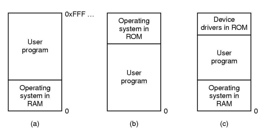
Three simple ways of organizing memory
Monoprogramming
Okay if
- Only have one thing to do
- Memory available approximately equates to memory required
- Otherwise,
- Poor CPU utilisation in the presence of I/O waiting
- Poor memory utilisation with a varied job mix
Fixed partitioning
Simple MM: Fixed, equal-sized partitions
- Any unused space in the partition is wasted
- Called internal fragmentation
- Processes smaller than main memory, but larger than a partition cannot run
Simple MM: Fixed, variable-sized partitions
Divide memory at boot time into a selection of different sized partitions
- Can base sizes on expected workload
Each partition has queue:
- Place process in queue for smallest partition that it fits in.
- Processes wait for when assigned partition is empty to start
Issue
- Some partitions may be idle
- Small jobs available, but only large partition free
- Workload could be unpredictable
- Some partitions may be idle
Alternative queue strategy
Single queue, search for any jobs that fit
Small jobs in large partition if necessary
Increases internal memory fragmentation
Fixed Partition Summary
- Simple
- Easy to implement
- Can result in poor memory utilisation
- Due to internal fragmentation
- Used on IBM System 360 operating system (OS/MFT)
- Announced 6 April, 1964
- Still applicable for simple embedded systems
- Static workload known in advance
Dynamic Partitioning
Partitions are of variable length
- Allocated on-demand from ranges of free memory
Process is allocated exactly what it needs
- Assumes a process knows what it needs
We end up with unusable holes (external fragmentation)
Classic Approach
Represent available memory as a linked list of available “holes” (free memory ranges).
- Base, size
- Kept in order of increasing address
- Simplifies merging of adjacent holes into larger holes.
- List nodes be stored in the “holes” themselves
Dynamic Partitioning Placement Algorithm
First-fit algorithm
- Scan the list for the first entry that fits
- If greater in size, break it into an allocated and free part
- Intent: Minimise amount of searching performed
- Aims to find a match quickly
- Biases allocation to one end of memory
- Tends to preserve larger blocks at the end of memory
Next-fit
- Like first-fit, except it begins its search from the point in list where the last request succeeded instead of at the beginning.
- (Flawed) Intuition: spread allocation more uniformly over entire memory to avoid skipping over small holes at start of memory
- Performs worse than first-fit as it breaks up the large free space at end of memory.
Best-fit algorithm
- Chooses the block that is closest in size to the request
- Performs worse than first-fit
- Has to search complete list
- does more work than first-fit
- Since smallest block is chosen for a process, the smallest amount of external fragmentation is left
- Create lots of unusable holes
Worst-fit algorithm
- Chooses the block that is largest in size (worst-fit)
- (whimsical) idea is to leave a usable fragment left over
- Poor performer
- Has to do more work (like best fit) to search complete list
- Does not result in significantly less fragmentation
Dynamic Partition Allocation Algorithm Summary
- First-fit generally better than the others and easiest to implement
Compaction
We can reduce external fragmentation by compaction
- Shuffle memory contents to place all free memory together in one large block.
- Only if we can relocate running programs?
- Pointers?
Generally requires hardware support
When are memory addresses bound?
- Compile/link time
- Compiler/Linker binds the addresses
- Must know “run” location at compile time
- Recompile if location changes
- Load time
- Compiler generates relocatable code
- Loader binds the addresses at load time
- Run time
- Logical compile-time addresses translated to physical addresses by special hardware.
Hardware Support for Runtime Binding and Protection
- For process B to run using logical addresses
- Process B expects to access addresses from zero to some limit of memory size
- Need to add an appropriate offset to its logical addresses
- Achieve relocation
- Protect memory “lower” than B
- Must limit the maximum logical address B can generate
- Protect memory “higher” than B
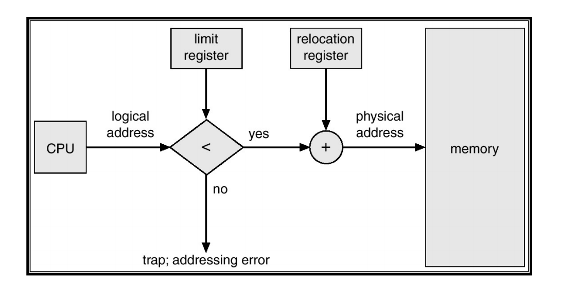
Base and Limit Register
- Also called
- Base and bound registers
- Relocation and limit registers
- Base and limit registers
- Restrict and relocate the currently active process
- Base and limit registers must be changed at
- Load time
- Relocation (compaction time)
- On a context switch
- Pro
- Supports protected multi-processing (-tasking)
- Cons
- Physical memory allocation must still be contiguous
- The entire process must be in memory
- Do not support partial sharing of address spaces
- No shared code, libraries, or data structures between processes
Thus far, we have a system suitable for a batch system
- Limited number of dynamically allocated processes
- Enough to keep CPU utilised
- Relocated at runtime
- Protected from each other
Swapping
A process can be swapped temporarily out of memory to a backing store, and then brought back into memory for continued execution.
Backing store – fast disk large enough to accommodate copies of all memory images for all users; must provide direct access to these memory images.
Can prioritize – lower-priority process is swapped out so higher-priority process can be loaded and executed.
Major part of swap time is transfer time; total transfer time is directly proportional to the amount of memory swapped.
- slow
we assume a process is smaller than memory
Virtual Memory – Paging Overview
Partition physical memory into small equal sized chunks
- Called frames
Divide each process’s virtual (logical) address space into same size chunks
- Called pages
- Virtual memory addresses consist of a page number and offset within the page
OS maintains a page table
contains the frame location for each page
Used by hardware to translate each virtual address to physical address
The relation between virtual addresses and physical memory addresses is given by page table
Process’s physical memory does not have to be contiguous
No external fragmentation
Small internal fragmentation (in last page)
Allows sharing by mapping several pages to the same frame
Abstracts physical organisation
- Programmer only deal with virtual addresses
Minimal support for logical organisation
- Each unit is one or more pages
Virtual Memory
Memory Management Unit(or TLB)
Page-based VM
Virtual Memory
- Divided into equalsized pages
- A mapping is a translation between
- A page and a frame
- A page and null
- Mappings defined at runtime – They can change
- Address space can have holes
- Process does not have to be contiguous in physical memory
Physical Memory
- Divided into equal-sized frames
Typical Address Space Layout
- Stack region is at top, and can grow down
- Heap has free space to grow up
- Text is typically read-only
- Kernel is in a reserved, protected, shared region
- 0-th page typically not used
Page Faults
Referencing an invalid page triggers a page fault – An exception handled by the OS
Broadly, two standard page fault types
- Illegal Address (protection error)
- Signal or kill the process
- Page not resident
- Get an empty frame
- Load page from disk
- Update page (translation) table (enter frame #, set valid bit, etc.)
- Restart the faulting instruction
Shared Pages
- Private code and data
- Each process has own copy of code and data
- Code and data can appear anywhere in the address space
- Shared code
- Single copy of code shared between all processes executing it
- Code must not be self modifying
- Code must appear at same address in all processes
Page Table Structure
Page table is (logically) an array of frame numbers
- Index by page number
Each page-table entry (PTE) also has other bits
- Present/Absent bit
- Also called valid bit, it indicates a valid mapping for the page
- Modified bit
- Also called dirty bit, it indicates the page may have been modified in memory
- Reference bit
- Indicates the page has been accessed
- Protection bits
- Read permission, Write permission, Execute permission
- Or combinations of the above
- Caching bit
- Use to indicate processor should bypass the cache when accessing memory
- Example: to access device registers or memory
- Use to indicate processor should bypass the cache when accessing memory
Address Translation
Every (virtual) memory address issued by the CPU must be translated to physical memory
- Every load and every store instruction
- Every instruction fetch
Need Translation Hardware
In paging system, translation involves replace page number with a frame number
Page Tables
- Page tables are implemented as data structures in main memory
- Most processes do not use the full 4GB address space
- We need a compact representation that does not waste space
- Three basic schemes
- Use data structures that adapt to sparsity
- Use data structures which only represent resident pages
- Use VM techniques for page tables (details left to extended OS)
Two-level Page Table
2nd –level page tables representing unmapped pages are not allocated – Null in the top-level page table
Alternative: Inverted Page Table
“Inverted page table” is an array of page numbers sorted (indexed) by frame number (it’s a frame table).
Algorithm
- Compute hash of page number
- Extract index from hash table
- Use this to index into inverted page table
- Match the PID and page number in the IPT entry
- If match, use the index value as frame # for translation
- If no match, get next candidate IPT entry from chain field
- If NULL chain entry $\Rightarrow$ page fault
Properties of IPTs
- IPT grows with size of RAM, NOT virtual address space
- Frame table is needed anyway (for page replacement, more later)
- Need a separate data structure for non-resident pages
- Saves a vast amount of space (especially on 64-bit systems)
- Used in some IBM and HP workstations
Improving the IPT: Hashed Page Table
- Retain fast lookup of IPT – A single memory reference in best case
- Retain page table sized based on physical memory size (not virtual)
- Enable efficient frame sharing
- Support more than one mapping for same frame
Sizing the Hashed Page Table
- HPT sized based on physical memory size
- With sharing
- Each frame can have more than one PTE
- More sharing increases number of slots used – Increases collision likelihood
- However, we can tune HPT size based on:
- Physical memory size
- Expected sharing
- Hash collision avoidance.
- HPT a power of 2 multiple of number of physical memory frame
VM Implementation Issue
Performance
Each virtual memory reference can cause two physical memory accesses
- One to fetch the page table entry
- One to fetch/store the data
$\Rightarrow$ Intolerable performance impact!!
Solution:
- High-speed cache for page table entries (PTEs)
- Called a translation look-aside buffer (TLB)
- Contains recently used page table entries
- Associative, high-speed memory, similar to cache memory
- May be under OS control (unlike memory cache)
TLB
Translation Lookaside Buffer
- Given a virtual address, processor examines the TLB
- If matching PTE found (TLB hit), the address is translated
- Otherwise (TLB miss), the page number is used to index the process’s page table
- If PT contains a valid entry, reload TLB and restart
- Otherwise, (page fault) check if page is on disk
- If on disk, swap it in
- Otherwise, allocate a new page or raise an exception
TLB properties
Page table is (logically) an array of frame numbers
TLB holds a (recently used) subset of PT entries
- Each TLB entry must be identified (tagged) with the page # it translates
- Access is by associative lookup:
- All TLB entries’ tags are concurrently compared to the page #
- TLB is associative (or content-addressable) memory
TLB may or may not be under direct OS control
- Hardware-loaded TLB
- On miss, hardware performs PT lookup and reloads TLB
- Example: x86, ARM
- Software-loaded TLB
- On miss, hardware generates a TLB miss exception, and exception handler reloads TLB
- Example: MIPS, Itanium (optionally)
- Hardware-loaded TLB
TLB size: typically 64-128 entries
Can have separate TLBs for instruction fetch and data access
TLBs can also be used with inverted page tables (and others)
TLB and context switching
- TLB is a shared piece of hardware
- Normal page tables are per-process (address space)
- TLB entries are process-specific
- On context switch need to flush the TLB (invalidate all entries)
- high context-switching overhead (Intel x86)
- or tag entries with address-space ID (ASID)
- called a tagged TLB
- used (in some form) on all modern architectures
- TLB entry: ASID, page #, frame #, valid and write-protect bits
- On context switch need to flush the TLB (invalidate all entries)
TLB effect
Without TLB
Average number of physical memory references per virtual reference
= 2
With TLB (assume 99% hit ratio)
Average number of physical memory references per virtual reference
= 0.99 * 1+ 0.01 * 2
= 1.01
Demand Paging/Segmentation
- With VM, only parts of the program image need to be resident in memory for execution
- Can transfer presently unused pages/segments to disk
- Reload non-resident pages/segment on demand.
- Reload is triggered by a page or segment fault
- Faulting process is blocked and another scheduled
- When page/segment is resident, faulting process is restarted
- May require freeing up memory first
- Replace current resident page/segment
- How determine replacement “victim”?
- If victim is unmodified (“clean”) can simply discard it
- This is reason for maintaining a “dirty” bit in the PT
Why does demand paging/segmentation work?
- Program executes at full speed only when accessing the resident set.
- TLB misses introduce delays of several microseconds
- Page/segment faults introduce delays of several milliseconds
Answer
- Less physical memory required per process
- Can fit more processes in memory
- Improved chance of finding a runnable one
- Principle of locality
Principle of Locality
An important observation comes from empirical studies of the properties of programs.
- Programs tend to reuse data and instructions they have used recently.
- 90/10 rule – “A program spends 90% of its time in 10% of its code”
We can exploit this locality of references
An implication of locality is that we can reasonably predict what instructions and data a program will use in the near future based on its accesses in the recent past
Two different types of locality have been observed:
- Temporal locality: states that recently accessed items are likely to be accessed in the near future
- Spatial locality: says that items whose addresses are near one another tend to be referenced close together in time
Working Set
The pages/segments required by an application in a time window ($\Delta$)is called its memory working set.
Working set is an approximation of a programs’ locality
- if $\Delta$ too small will not encompass entire locality
- if $\Delta$ too large will encompass several localities
- if $\Delta = \infin\Rightarrow$ will encompass entire program.
- $\Delta$’s size is an application specific tradeoff
System should keep resident at least a process’s working set – Process executes while it remains in its working set
Working set tends to change gradually
- Get only a few page/segment faults during a time window
- Possible (but hard) to make intelligent guesses about which pieces will be needed in the future – May be able to pre-fetch page/segments
Thrashing
CPU utilisation tends to increase with the degree of multiprogramming – number of processes in system
Higher degrees of multiprogramming – less memory available per process
Some process’s working sets may no longer fit in RAM – Implies an increasing page fault rate
Eventually many processes have insufficient memory
- Can’t always find a runnable process
- Decreasing CPU utilisation
- System become I/O limited
This is called thrashing
$ \sum$working set sizes > total physical memory size
Recovery From Thrashing
In the presence of increasing page fault frequency and decreasing CPU utilisation
- Suspend a few processes to reduce degree of multiprogramming
- Resident pages of suspended processes will migrate to backing store
- More physical memory becomes available
- Resume suspended processes later when memory pressure eases
VM Management Policies
Operation and performance of VM system is dependent on a number of policies:
- Page table format (may be dictated by hardware)
- Multi-level
- Inverted/Hashed
- Page size (may be dictated by hardware)
- Fetch Policy
- Replacement policy
- Resident set size
- Minimum allocation
- Local versus global allocation
- Page cleaning policy
Page Size
Increasing page size
❌ Increases internal fragmentation – reduces adaptability to working set size
✅ Decreases number of pages – Reduces size of page tables
✅ Increases TLB coverage – Reduces number of TLB misses
❌ Increases page fault latency – Need to read more from disk before restarting process
✅ Increases swapping I/O throughput – Small I/O are dominated by seek/rotation delays
Optimal page size is a (work-load dependent) trade-off
Multiple page sizes provide flexibility to optimise the use of the TLB
- Large page sizes can be use for code
- Small page size for thread stacks
Most operating systems support only a single page size
- Dealing with multiple page sizes is hard!
Fetch Policy
Determines when a page should be brought into memory
Demand paging only loads pages in response to page faults – Many page faults when a process first starts
Pre-paging brings in more pages than needed at the moment
✅ Improves I/O performance by reading in larger chunks
❌ Wastes I/O bandwidth if pre-fetched pages aren’t used
❌ Especially bad if we eject pages in working set in order to pre-fetch unused pages.
❌ Hard to get right in practice
Replacement Policy
- Page removed should be the page least likely to be references in the near future
- Most policies attempt to predict the future behaviour on the basis of past behaviour
- Constraint: locked frames
- Kernel code
- Main kernel data structure
- I/O buffers
- Performance-critical user-pages (e.g. for DBMS)
- Frame table has a lock (or pinned) bit
Optimal Replacement policy
Toss the page that won’t be used for the longest time
❌ Impossible to implement
❌ Only good as a theoretic reference point:The closer a practical algorithm gets to optimal, the better
FIFO Replacement Policy
First-in, first-out: Toss the oldest page
✅ Easy to implement
❌ Age of a page is isn’t necessarily related to usage
Least Recently Used (LRU)
Toss the least recently used page
Assumes that page that has not been referenced for a long time is unlikely to be referenced in the near future
⚪ Will work if locality holds
⚪ Implementation requires a time stamp to be kept for each page, updated on every reference
❌ Impossible to implement efficiently
⚪ Most practical algorithms are approximations of LRU
Clock Page Replacement
Clock policy, also called second chance.
Employs a usage or reference bit in the frame table.
Set to one when page is used
While scanning for a victim, reset all the reference bits
Toss the first page with a zero reference bit
Issue
How do we know when a page is referenced?
Use the valid bit in the PTE:
- When a page is mapped (valid bit set), set the reference bit
- When resetting the reference bit, invalidate the PTE entry
- On page fault
- Turn on valid bit in PTE
- Turn on reference bit
- We thus simulate a reference bit in software
Performance
It terms of selecting the most appropriate replacement, they rank as follows:
- Optimal
- LRU
- Clock
- FIFO
Resident Set Size
How many frames should each process have?
Fixed Allocation
Gives a process a fixed number of pages within which to execute.
Isolates process memory usage from each other
When a page fault occurs, one of the pages of that process must be replaced.
❌ Achieving high utilisation is an issue – Some processes have high fault rate while others don’t use their allocation.
Variable Allocation
Number of pages allocated to a process varies over the lifetime of the process
Global Scope
Operating system keeps global list of free frames
Free frame is added to resident set of process when a page fault occurs
If no free frame, replaces one from any process
✅ Easiest to implement
✅ Adopted by many operating systems
✅ Automatic balancing across system
❌ Does not provide guarantees for important activities
Local Scope
Allocate number of page frames to a new process based on
- Application type
- Program request
- Other criteria (priority)
When a page fault occurs, select a page from among the resident set of the process that suffers the page fault
Re-evaluate allocation from time to time!
Cleaning Policy
Observation – Clean pages are much cheaper to replace than dirty pages
Demand cleaning
- A page is written out only when it has been selected for replacement
- High latency between the decision to replace and availability of free frame.
Precleaning
- Pages are written out in batches (in the background, the pagedaemon)
- Increases likelihood of replacing clean frames
- Overlap I/O with current activity
Multiprocessor Systems
Amdahl’s law
Given a proportion P of a program that can be made parallel, and the remaining serial portion (1-P), speedup by using N processors$\frac{1}{(1-P)+\frac{P}{N}}$
Types of Multiprocessors (MPs)
- UMA MP (Uniform Memory Access)
- Access to all memory occurs at the same speed for all processors.
- NUMA MP (Non-uniform memory access)
- Access to some parts of memory is faster for some processors than other parts of memory
Bus Based UMA
- Simplest MP is more than one processor on a single bus connect to memory
- Bus bandwidth becomes a bottleneck with more than just a few CPUs
- Each processor has a cache to reduce its need for access to memory
- Hope is most accesses are to the local cache
- Bus bandwidth still becomes a bottleneck with many CPUs
- With only a single shared bus, scalability can be limited by the bus bandwidth of the single bus - Caching only helps so much
- Alternative bus architectures do exist.
- They improve bandwidth available
- Don’t eliminate constraint that bandwidth is limited
Multi-core Processor
(Multi-core) share the same Bus interface
Multiprocessors can
- Increase computation power beyond that available from a single CPU
- Share resources such as disk and memory
However
- Assumes parallelizable workload to be effective
- Assumes not I/O bound
- Shared buses (bus bandwidth) limits scalability
- Can be reduced via hardware design
- Can be reduced by carefully crafted software behaviour
- Good cache locality together with limited data sharing where possible
How do we construct an OS for a multiprocessor?
Each CPU has its own OS?
- Statically allocate physical memory to each CPU
- Each CPU runs its own independent OS
- Share peripherals
- Each CPU (OS) handles its processes system calls
Used in early multiprocessor systems to ‘get them going’
- Simpler to implement
- Avoids CPU-based concurrency issues by not sharing
- Scales – no shared serial sections
- Modern analogy, virtualisation in the cloud.
Issues
- Each processor has its own scheduling queue
- We can have one processor overloaded, and the rest idle
- Each processor has its own memory partition
- We can a one processor thrashing, and the others with free memory
- No way to move free memory from one OS to another
- We can a one processor thrashing, and the others with free memory
Symmetric Multiprocessors (SMP)
- OS kernel run on all processors
- Load and resource are balance between all processors
- Including kernel execution
- Load and resource are balance between all processors
Issue: Real concurrency in the kernel
- Need carefully applied synchronisation primitives to avoid disaster
- One alternative: A single mutex that make the entire kernel a large critical section
- Only one CPU can be in the kernel at a time
- The “big lock” becomes a bottleneck when in-kernel processing exceeds what can be done on a single CPU
- Better alternative: identify largely independent parts of the kernel and make each of them their own critical section
- Allows more parallelism in the kernel
- Issue: Difficult task
- Code is mostly similar to uniprocessor code
- Hard part is identifying independent parts that don’t interfere with each other
- Remember all the inter-dependencies between OS subsystems.
- Lock contention can limit overall system performance
Test-and-Set
Hardware guarantees that the instruction executes atomically on a CPU.
Atomically: As an indivisible unit.
The instruction can not stop half way through
Test-and-Set on SMP
It does not work without some extra hardware support
A solution:
Hardware blocks all other CPUs from accessing the bus during the TSL instruction to prevent memory accesses by any other CPU.
- TSL has mutually exclusive access to memory for duration of instruction.
Test-and Set is a busy-wait synchronisation primitive * Called a spinlock
Issue:
- Lock contention leads to spinning on the lock
- Spinning on a lock requires blocking the bus which slows all other CPUs down
- Independent of whether other CPUs need a lock or no
- Caching does not help reduce bus contention
- Spinning on a lock requires blocking the bus which slows all other CPUs down
- Either TSL still blocks the bus
- Or TSL requires exclusive access to an entry in the local cache
Reducing Bus Contention
- Read before TSL
- Spin reading the lock variable waiting for it to change
- When it does, use TSL to acquire the lock
- Allows lock to be shared read-only in all caches until its released
- no bus traffic until actual release
- No race conditions, as acquisition is still with TSL.
- Test and set performs poorly once there is enough CPUs to cause contention for lock
- Expected
- Read before Test and Set performs better
- Performance less than expected
- Still significant contention on lock when CPUs notice release and all attempt acquisition
- Critical section performance degenerates
- Critical section requires bus traffic to modify shared structure
- Lock holder competes with CPU that’s waiting as they test and set, so the lock holder is slower
- Slower lock holder results in more contention
Cache Consistency
Cache consistency is usually handled by the hardware.
Spinning versus Blocking and Switching
- Spinning (busy-waiting) on a lock makes no sense on a uniprocessor
- The was no other running process to release the lock
- Blocking and (eventually) switching to the lock holder is the only sensible option.
- On SMP systems, the decision to spin or block is not as clear.
- The lock is held by another running CPU and will be freed without necessarily switching away from the requestor
Spinning versus Switching
Blocking and switching
- to another process takes time
- Save context and restore another
- Cache contains current process not new process
- Adjusting the cache working set also takes time
- TLB is similar to cache
- Switching back when the lock is free encounters the same again
Spinning wastes CPU time directly
Trade off
If lock is held for less time than the overhead of switching to and back
$\Rightarrow$ It’s more efficient to spin
$\Rightarrow$ Spinlocks expect critical sections to be short
$\Rightarrow$ No waiting for I/O within a spinlock
$\Rightarrow$ No nesting locks within a spinlock
Preemption and Spinlocks
- Critical sections synchronised via spinlocks are expected to be short
- Avoid other CPUs wasting cycles spinning
- What happens if the spinlock holder is preempted at end of holder’s timeslice
- Mutual exclusion is still guaranteed
- Other CPUs will spin until the holder is scheduled again!!!!!
$\Rightarrow$ Spinlock implementations disable interrupts in addition to acquiring locks to avoid lock-holder preemption
Scheduling
The scheduler decides who to run next. This process is sheduling
Application behaviour
Bursts of CPU usage alternate with periods of I/O wait
a) CPU-Bound process
- Spends most of its computing
- Time to completion largely determined by received CPU time
b) I/O-Bound process
- Spend most of its time waiting for I/O to complete
- Small bursts of CPU to process I/O and request next I/O
- Time to completion largely determined by I/O request time
- We need a mix of CPU-bound and I/O-bound processes to keep both CPU and I/O systems busy
- Process can go from CPU- to I/O-bound (or vice versa) in different phases of execution
Key Insights
Choosing to run an I/O-bound process delays a CPU-bound process by very little
Choosing to run a CPU-bound process prior to an I/O-bound process delays the next I/O request significantly
- No overlap of I/O waiting with computation
- Results in device (disk) not as busy as possible
- Generally, favour I/O-bound processes over CPU-bound processes
- Generally, a scheduling decision is required when a process (or thread) can no longer continue, or when an activity results in more than one ready process
Preemptive versus Non-preemptive Scheduling
Non-preemptive
- Once a thread is in the running state, it continues until it completes, blocks on I/O, or voluntarily yields the CPU
- A single process can monopolised the entire system
Preemptive Scheduling (responsive system) - Current thread can be interrupted by OS and moved to ready state.
- Usually after a timer interrupt and process has exceeded its maximum run time
- Can also be as a result of higher priority process that has become ready (after I/O interrupt).
- Ensures fairer service as single thread can’t monopolise the system
- Requires a timer interrupt
Categories of Scheduling Algorithms
Batch Systems
- No users directly waiting, can optimise for overall machine performance
Interactive Systems
- Users directly waiting for their results, can optimise for users perceived performance
Realtime Systems
- Jobs have deadlines, must schedule such that all jobs (predictably) meet their deadlines
Goals of Scheduling Algorithms
All Algorithms
- Fairness
- Give each process a fair share of the CPU
- Policy Enforcement
- What ever policy chosen, the scheduler should ensure it is carried out
- Balance/Efficiency
- Try to keep all parts of the system busy
- Interactive Algorithms
- Minimise response time
- Response time is the time difference between issuing a command and getting the result
- E.g selecting a menu, and getting the result of that selection
- Response time is important to the user’s perception of the performance of the system.
- Response time is the time difference between issuing a command and getting the result
- Provide Proportionality
- Proportionality is the user expectation that short jobs will have a short response time, and long jobs can have a long response time.
- Generally, favour short jobs
- Real-time Algorithms
- Must meet deadlines
- Each job/task has a deadline.
- A missed deadline can result in data loss or catastrophic failure
- Aircraft control system missed deadline to apply brakes
- Provide Predictability
- For some apps, an occasional missed deadline is okay – E.g. DVD decoder
- Predictable behaviour allows smooth DVD decoding with only rare skips
- Must meet deadlines
Interactive scheduling
Round Robin Scheduling
- Each process is given a timeslice to run in
- When the timeslice expires, the next process preempts the current process, and runs for its timeslice, and so on
- The preempted process is placed at the end of the queue
- Implemented with
- A ready queue
- A regular timer interrupt
Pros – Fair, easy to implement
Con – Assumes everybody is equal
What should the timeslice be?
Too short
- Waste a lot of time switching between processes
- Example: timeslice of 4ms with 1 ms context switch = 20% round robin overhead
Too long
- System is not responsive
- Example: timeslice of 100ms – If 10 people hit “enter” key simultaneously, the last guy to run will only see progress after 1 second.
- Degenerates into FCFS if timeslice longer than burst length
Priorities
- Each Process (or thread) is associated with a priority
- Provides basic mechanism to influence a scheduler decision:
- Scheduler will always chooses a thread of higher priority over lower priority
- Priorities can be defined internally or externally
- Internal: e.g. I/O bound or CPU bound
- External: e.g. based on importance to the user
- Usually implemented by multiple priority queues, with round robin on each queue
- Con
- Low priorities can starve
- Need to adapt priorities periodically
- Based on ageing or execution history
- Need to adapt priorities periodically
- Low priorities can starve
Traditional UNIX Scheduler
Two-level scheduler
- High-level scheduler schedules processes between memory and disk
- Low-level scheduler is CPU scheduler
- Based on a multilevel queue structure with round robin at each level
- The highest priority (lower number) is scheduled
- Priorities are re-calculated once per second, and re-inserted in appropriate queue
- Avoid starvation of low priority threads
- Penalise CPU-bound threads
- Priority = CPU_usage +nice +base
- CPU_usage = number of clock ticks
- Nice is a value given to the process by a user to permanently boost or reduce its priority ( Reduce priority of background jobs)
- Base is a set of hardwired, negative values used to boost priority of I/O bound system activities
Single Shared Ready Queue
Pros
- Simple
- Automatic load balancing
Cons
- Lock contention on the ready queue can be a major bottleneck
- Due to frequent scheduling or many CPUs or both
- Not all CPUs are equal
- The last CPU a process ran on is likely to have more related entries in the cache
Affinity Scheduling
Basic Idea – Try hard to run a process on the CPU it ran on last time
One approach: Multiple Queue Multiprocessor Scheduling
Multiple Queue SMP Scheduling
- Each CPU has its own ready queue
- Coarse-grained algorithm assigns processes to CPUs
- Defines their affinity, and roughly balances the load
- The bottom-level fine-grained scheduler:
- Is the frequently invoked scheduler (e.g. on blocking on I/O, a lock, or exhausting a timeslice)
- Runs on each CPU and selects from its own ready queue
- Ensures affinity
- If nothing is available from the local ready queue, it runs a process from another CPUs ready queue rather than go idle
- Termed “Work stealing”
✅ No lock contention on per-CPU ready queues in the (hopefully) common case
✅ Load balancing to avoid idle queues
✅ Automatic affinity to a single CPU for more cache friendly behaviour
I/O Management
I/O Devices
There exists a large variety of I/O devices:
- Many of them with different properties
- They seem to require different interfaces to manipulate and manage them
- We don’t want a new interface for every device
- Diverse, but similar interfaces leads to code duplication
- Challenge:
- Uniform and efficient approach to I/O
Device Drivers
Drivers classified into similar categories
- Block devices and character (stream of data) device
OS defines a standard (internal) interface to the different classes of devices
- Example: USB Human Input Device (HID) class specifications
- human input devices follow a set of rules making it easier to design a standard interface.
Device drivers job
- translate request through the device-independent standard interface (open, close, read, write) into appropriate sequence of commands (register manipulations) for the particular hardware
- Initialise the hardware at boot time, and shut it down cleanly at shutdown
After issuing the command to the device, the device either
- Completes immediately and the driver simply returns to the caller
- Or, device must process the request and the driver usually blocks waiting for an I/O complete interrupt.
Drivers are thread-safe as they can be called by another process while a process is already blocked in the driver
- Thead-safe: Synchronised…
Device-Independent I/O Software
There is commonality between drivers of similar classes
Divide I/O software into device-dependent and device-independent I/O software
Device independent software includes
- Buffer or Buffer-cache management
- TCP/IP stack
- Managing access to dedicated devices
- Error reporting
I/O Device Handling
Data rate
- May be differences of several orders of magnitude between the data transfer rates
Driver $\Leftrightarrow$ Kernel Interface
Major Issue is uniform interfaces to devices and kernel
- Uniform device interface for kernel code
- Allows different devices to be used the same way
- Allows internal changes to device driver with fear of breaking kernel code
- Uniform kernel interface for device code
- Drivers use a defined interface to kernel services (e.g. kmalloc, install IRQ handler, etc.)
- Allows kernel to evolve without breaking existing drivers
- Together both uniform interfaces avoid a lot of programming implementing new interfaces
- Retains compatibility as drivers and kernels change over time.
Interrupts
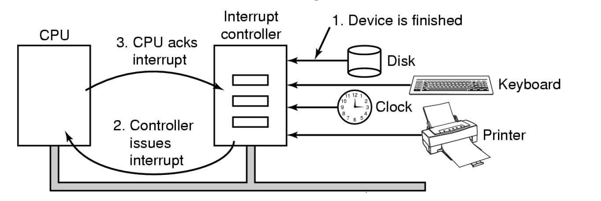
- Devices connected to an Interrupt Controller via lines on an I/O bus (e.g. PCI)
- Interrupt Controller signals interrupt to CPU and is eventually acknowledged.
- Exact details are architecture specific.
I/O Interaction
Programmed I/O
- Also called polling, or busy waiting
- I/O module (controller) performs the action, not the processor
- Sets appropriate bits in the I/O status register
- No interrupts occur
- Processor checks status until operation is complete
- Wastes CPU cycles
Interrupt-Driven I/O
- Processor is interrupted when I/O module (controller) ready to exchange data
- Processor is free to do other work
- No needless waiting
- Consumes a lot of processor time because every word read or written passes through the processor
Direct Memory Access (DMA)
- Transfers data directly between Memory and Device
- CPU not needed for copying
- Transfers a block of data directly to or from memory
- An interrupt is sent when the task is complete
- The processor is only involved at the beginning and end of the transfer
DMA Considerations
✅ Reduces number of interrupts
- Less (expensive) context switches or kernel entry-exits
❌ Requires contiguous regions (buffers)
- Copying
- Some hardware supports “Scatter-gather”
Synchronous/Asynchronous
Shared bus must be arbitrated (hardware)
– CPU cache reduces (but not eliminates) CPU need for bus
I/O Management Software
I/O Software Layers
Interrupt Handlers
- Interrupt handlers
- Can execute at (almost) any time
- Raise (complex) concurrency issues in the kernel
- Can propagate to userspace (signals, upcalls), causing similar issues
- Generally structured so I/O operations block until interrupts notify them of completion
kern/dev/lamebus/lhd.c
- Can execute at (almost) any time
Interrupt Handler Steps
- Save Registers not already saved by hardware interrupt mechanism
- (Optionally) set up context for interrupt service procedure
- Typically, handler runs in the context of the currently running process
- No expensive context switch
- Set up stack for interrupt service procedure
- Handler usually runs on the kernel stack of current process
- Or “nests” if already in kernel mode running on kernel stack
- Ack/Mask interrupt controller, re-enable other interrupts
- Implies potential for interrupt nesting.
- Run interrupt service procedure
- Acknowledges interrupt at device level
- Figures out what caused the interrupt
- Received a network packet, disk read finished, UART transmit queue empty
- If needed, it signals blocked device driver
- In some cases, will have woken up a higher priority blocked thread
- Choose newly woken thread to schedule next.
- Set up MMU context for process to run next
- What if we are nested?
- Load new/original process’ registers
- Re-enable interrupt; Start running the new process
Sleeping in Interrupts
An interrupt generally has no
context
(runs on current kernel stack)
- Unfair to sleep on interrupted process (deadlock possible)
- Where to get context for long running operation?
- What goes into the ready queue?
What to do?
- Top and Bottom Half
- Linux implements with tasklets and workqueues
- Generically, in-kernel thread(s) handle long running kernel operations.
Top/Half Bottom Half
- Top Half
- Interrupt handler
- remains short
- Bottom half
- Is preemptable by top half (interrupts)
- performs deferred work (e.g. IP stack processing)
- Is checked prior to every kernel exit
- signals blocked processes/threads to continue
- Enables low interrupt latency
- Bottom half can’t block
Deferring Work on In-kernel Threads
- Interrupt
- handler defers work onto in-kernel thread
- In-kernel thread handles deferred work (DW)
- Scheduled normally
- Can block
- Both low interrupt latency and blocking operations
Buffering
No Buffering
- Process must read/write a device a byte/word at a time
- Each individual system call adds significant overhead
- Process must what until each I/O is complete
- Blocking/interrupt/waking adds to overhead.
- Many short runs of a process is inefficient (poor CPU cache temporal locality)
User-level Buffering
- Process specifies a memory buffer that incoming data is placed in until it fills
- Filling can be done by interrupt service routine
- Only a single system call, and block/wakeup per data buffer
- Much more efficient
- Issues
- What happens if buffer is paged out to disk
- Could lose data while unavailable buffer is paged in
- Could lock buffer in memory (needed for DMA), however many processes doing I/O reduce RAM available for paging. Can cause deadlock as RAM is limited resource
- Consider write case
- When is buffer available for re-use?
- Either process must block until potential slow device drains buffer
- or deal with asynchronous signals indicating buffer drained
- When is buffer available for re-use?
- What happens if buffer is paged out to disk
Single Buffer
Operating system assigns a buffer in kernel’s memory for an I/O request
In a stream-oriented scenario
- Used a line at time
- User input from a terminal is one line at a time with carriage return signaling the end of the line
- Output to the terminal is one line at a time
Block-oriented
- Input transfers made to buffer
- Block copied to user space when needed
- Another block is written into the buffer
- Read ahead
User process can process one block of data while next block is read in
Swapping can occur since input is taking place in system memory, not user memory
Operating system keeps track of assignment of system buffers to user processes
Assume
- T is transfer time for a block from device
- C is computation time to process incoming block
- M is time to copy kernel buffer to user buffer
Computation and transfer can be done in parallel
Speed up with buffering
What happens if kernel buffer is full
- the user buffer is swapped out, or
- The application is slow to process previous buffer and more data is received???
- => We start to lose characters or drop network packets
Double Buffer
- Use two system buffers instead of one
- A process can transfer data to or from one buffer while the operating system empties or fills the other buffer
Double Buffer Speed Up
Computation and Memory copy can be done in parallel with transfer
Speed up with double buffering
Usually M is much less than T giving a favourable result
May be insufficient for really bursty traffic
- Lots of application writes between long periods of computation
- Long periods of application computation while receiving data
- Might want to read-ahead more than a single block for disk
Circular Buffer
- More than two buffers are used
- Each individual buffer is one unit in a circular buffer
- Used when I/O operation must keep up with process
Notice that buffering, double buffering, and circular buffering are all Bounded-Buffer Producer-Consumer Problems
Reference:
UNSW COMP3231 2020 lecture slides